CivilLasers のTTL レーザーモジュールの配線手順
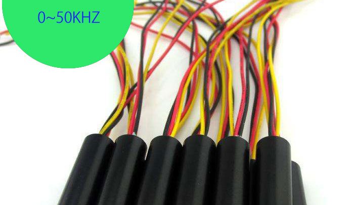
TTL 変調します レーザー モジュール 3本の電線があります.
1. 赤い糸:赤い糸は陽極をつなぎます;
2. 黒色線:黒色線は陰極をつなぎます;
3. 黄色線:黄色線はまっすぐな信号ラインをつないで、マイナスの信号ラインは黒色線をつなぎます;
.jpg)
連続して仕事モデル(1mw~10mw Laser module)
1. 赤い糸:赤い糸は陽極をつなぎます;
2. 黒色線:黒色線は陰極をつなぎます;
3. 黄色線が空いています;
連続して仕事モデル (10mw~100mw Laser module)
1. 赤色線は黄色線とと一緒に電源の陽極をつなぎます;
2. 黒色線:黒色線は陰極をつなぎます;
TTL モジュール 変調(1kHZ~1000kHZ / 2V-5V)
1. 赤い糸:赤い糸は陽極をつなぎます;
2. 黒色線:黒色線は陰極をつなぎます;
3. 黄色線は信号ラインの陽極をつなぎます;
4. 黒色線は信号ラインの陰極をつなぎます;
(Note: In Modulation mode, the black line be connected the negative power supply and the negative signal line;)
Modulation module instructions
1. When in use, connect the red and yellow line, the module will be bright, and in continuous work mode;
2. When you want modulation, connect the negative of signal line to black line, and positive to yellow line, keep the red line suspended, then the module in modulation mode;
3. Signal input should be in the range of 300KHZ;
4. The input voltage of modulation work is 3.3V, continuous work input voltage is 3.3V.
.jpg)
.jpg)